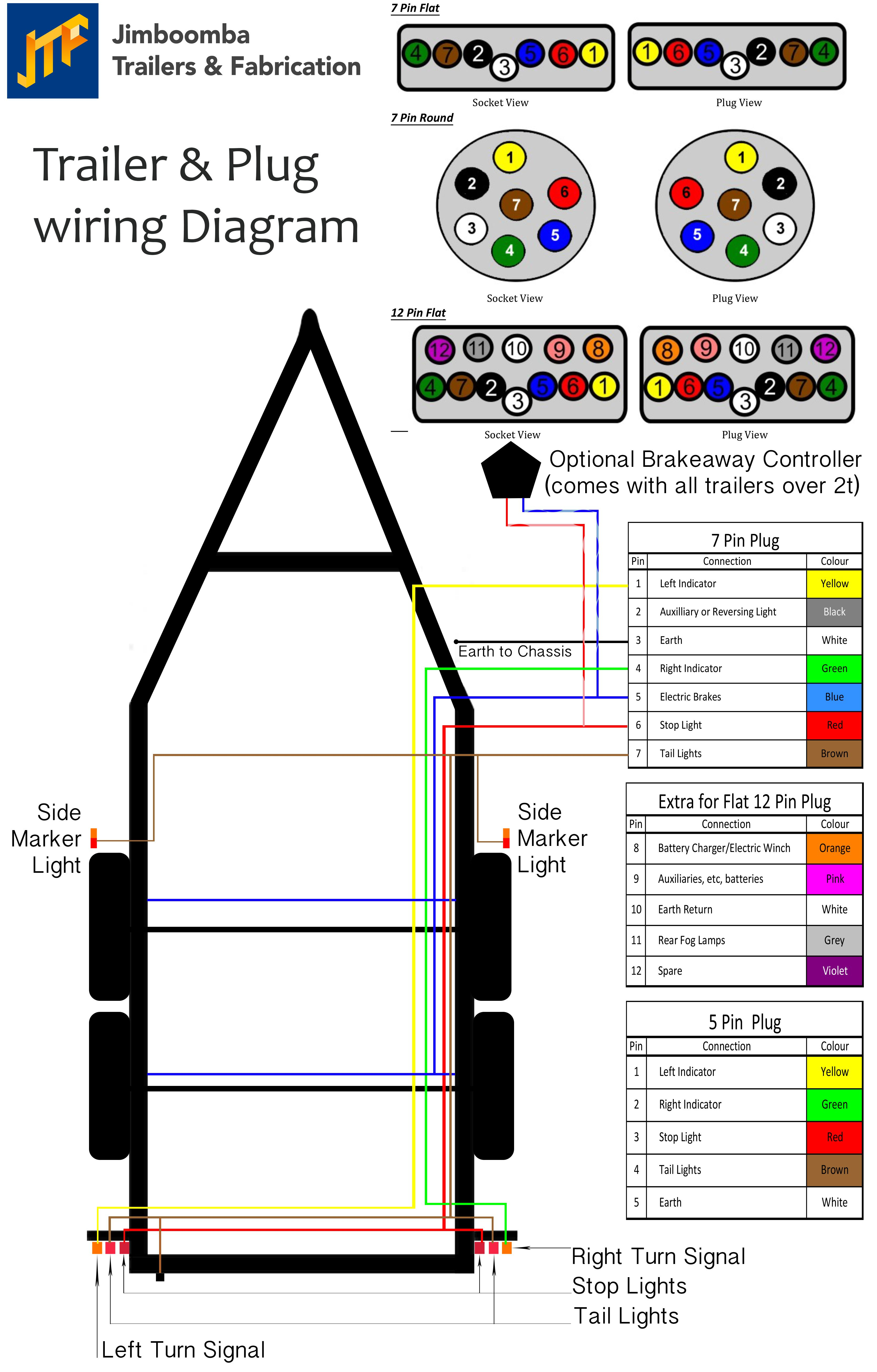
7 Pin Brake Controller Wiring Diagram

nest Hello Wiring Diagram, Nest Hello Advanced Wiring Diagram, 6.25 MB, 04:33, 63,749, gt8monster, 2018-06-16T10:14:46.000000Z, 19, Nest Hello Doorbell: 18 Questions/Answers You Need To Know - Smart Home Point, www.smarthomepoint.com, 1057 x 852, png, nest diagram hello doorbell wiring google camera chimes chime install multiple lh4 googleusercontent answers questions know need pre, 20, %ef%bb%bfnest-hello-wiring-diagram, Anime Arts
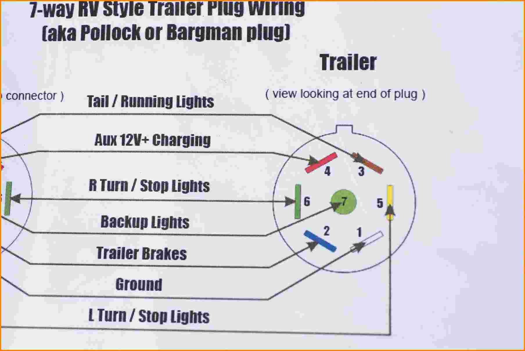
If your trailer has more than 4. The center pin is usually for the yellow wire but it is the aux pin that could power just about anything. Usually, it is the trailer's back up lights. This is okay if your state does not require that your trailer have back up lights.
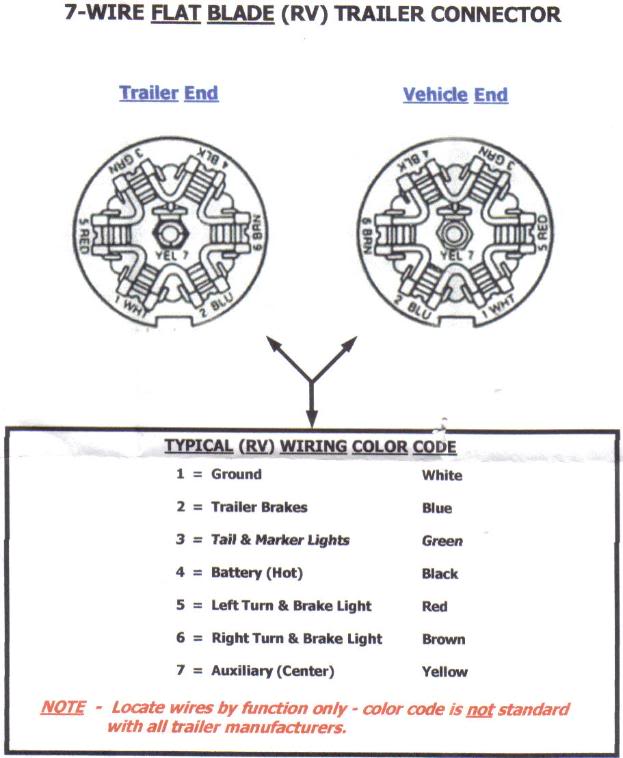
7 pin brake controller wiring diagram. Seven pin trailer wiring diagram. Sometimes, the cables will cross. Important facts to remember 1. The four wires control the turn signals, brake lights and taillights or running lights. Effectively read a wiring diagram, one offers to learn how the components in the program operate. For example , if a module will be powered up and it also sends out a signal of fifty percent the voltage plus the technician will not know this, he would think he provides a problem, as he would expect the 12v signal. 7 pin gives you aux charging, backup lights, and trailer brake control while the 4 pin gives you the basic wiring (running, l/r turn, ground). If you have the 7 pin connector on the maverick and only have 4.
7 Pin Trailer Brake Wiring Diagram | Trailer Wiring Diagram

Trailer Brake Wiring Diagram 7 Way | Wiring Diagram

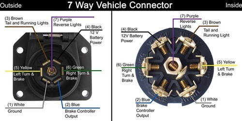
7-Way RV and 7-Way Round Pin Brake Controller Output Wire Connection Location. | etrailer.com
43 7 Pin Trailer Brake Wiring - Wiring Diagram Source Online

Brake Controller & 7-pin trailer Install 3rd Gen 4Runner - YotaTech Forums

Where To Connect The Brake Controller To The 7-Way Trailer Connector On The Tow Vehicle

7 Pin Trailer Connector Brake - WIRGREM

Wiring Diagram For A 7 Wire Trailer Plug | Trailer Wiring Diagram

7 Pin Trailer Wiring Diagram With Brakes | Cadician's Blog

Electric Trailer Brake Controller Wiring Diagram | Trailer Wiring Diagram
