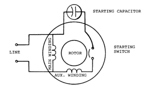
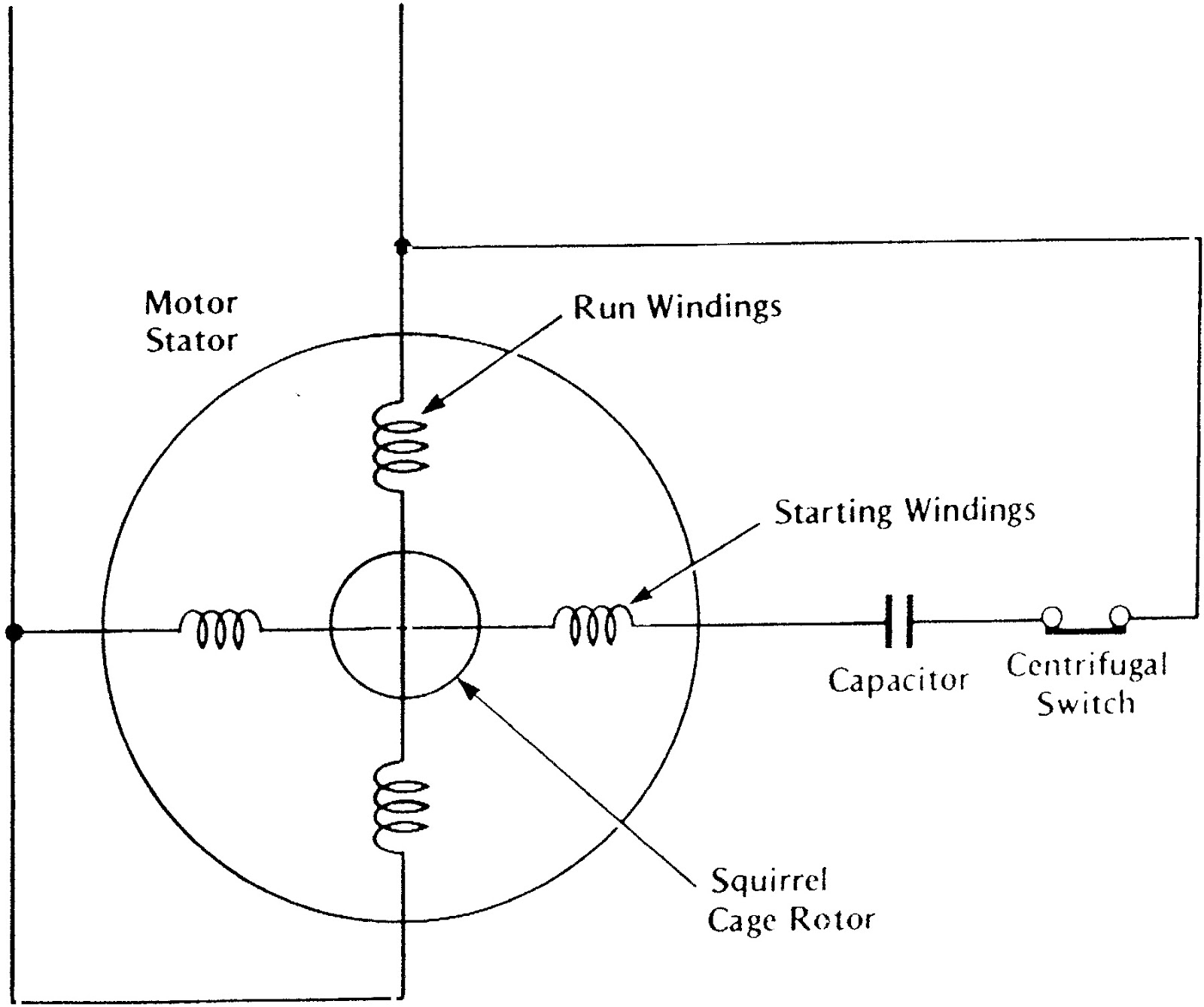
1 Phase Induction Motor Wiring Diagram
Rj11 Socket Wiring Diagram Australia, How to punch down an RJ11 Telephone Jack, 6.36 MB, 04:38, 387,634, CableSupply.com, 2009-08-05T00:16:07.000000Z, 19, Rj11 Socket Wiring Diagram Australia | Computacion, Redes de computadoras, Computadoras, www.pinterest.com.mx, 728 x 783, jpeg, rj11 wiring rj45 diagram cable ethernet usb jack pinout adapter cat5 female male convert using rs485 cat wires code socket, 20, rj11-socket-wiring-diagram-australia, Anime Arts
Diagram dd6 diagram dd7 m 1~ ln e diagram dd8 ln e l1 l2 l3 s/c z1 u2 z2 u1 cap. Some standard frame induction motor diagrams have been included for ease of presentation. Er 1, 2, 4, 5 ocd/e. If a primary resistance starter is connected to the motor so that the voltage to the motor is reduced to 291 v for starting, determine the:
(b) starting current taken by the >motor. Go forth and spin ac motors! Find the end of each coil with a multimeter, connect one side of each coil to the power and the other side to the capacitor. Connect the other side of the ac to one side of the capacitor. Hot and common don't matter at all. Don't work on the motor with the power connected! Be careful with the capacitor. When the stator winding of a single phase induction motor is connected to single phase ac supply, a magnetic field is developed, the axis of this magnetic field is stationary in the horizontal direction as shown in the figure 4. Diagram dd6 diagram dd8 m 1~ ln e diagram dd9 m 1~ ln e white brown blue l1 l2 n s/c.
Types of Single Phase Induction Motors | Single Phase Induction Motor Wiring Diagram
Clarke Single Phase Induction Motor Wiring Diagram

Single-Phase Induction Motor Working | Electrical Academia
Clarke Single Phase Induction Motor Wiring Diagram
What is the wiring of a single-phase motor? - Quora
What is the wiring of a single-phase motor? - Quora
Clarke Single Phase Induction Motor Wiring Diagram
Single Phase Induction motor Winding Diagram | Electrical circuit diagram, Electrical diagram

Types of Single Phase Induction Motors | Single Phase Induction Motor Wiring Diagram

Ac - Correct Wiring Of 1 Phase 220V Electrical Motor - Electrical - Single Phase Motor Wiring
